
Open Shortest Path First (OSPF) is a standard Internet routing protocol that is designed to find the best or least cost path for a packet or circuit to a destination system. In OSPF, each routing system on a network maintains a link state database reflecting the state of every trunk (link) in the network. Using this database, it then builds a spanning tree representation of each path and cost.
PNNI 1.0 (Private Network to Network Interface) is a standard created by the ATM forum that is based on the routing principles of OSPF, but extended for ATM to ensure Quality of Service for connections. PNNI ensures that a PVC or SVC gets the least cost path through a network that meets all the QoS requirements of that circuit, while maximizing trunk bandwidth utilization.
VNN (Virtual Network Navigator) is a Lucent proprietary protocol that further extends the functionality of PNNI 1.0. VNN allows for VPNs and special trunk types, user configurable CAC parameters etc. Lucent switches use VNN inside an all Lucent network, and use PNNI to negotiate paths through non-Lucent switches.
The current information we have on VNN was inferred from several Lucent functional specifications and the ATM standard PNNI documentation. Exact routing algorithms and CAC calculations are not known at this time, but as long as we meet the functional requirements, this should not matter.
The OSPF manager works very closely with the Virtual Channel Manager and the ATM and Frame Relay layers to keep an accurate picture of the state of the network. The ATM and Frame Relay layers pass information to OSPF any time the state of a trunk changes (up, down, bandwidth, congestion changes, etc). This information is passed to every other switch in the simulation, and is used by the OSPF routing algorithm when the VC Manager requests a path.

When a switch is started, its OSPF spanning tree (a tree of least cost paths) and the Link State Database are empty. When the student provisions a direct ATM or Frame trunk, OSPF is notified that a link now available on that Lport though a call to OSPF_LinkStateChange(). OSPF then exchanges 'hello' packets with the switch on the other side of the trunk. This identifies the characteristics (bandwidth, QoS, cell delay etc, cost) of the link and lport at each end.
OSPF on each switch then notifies every other switch in the network about this new link through a 'reliable flood' of Link State Database Update packets. These packets propagate throughout the network, with each switch updating its own copy of the database as required. The eventual result of this flooding is that every switch is aware of every trunk in the network. Each switch effectively has an identical copy of the link state database.
When the VC Manager requests a path to a destination switch for a new PVC or SVC, it calls OSPF_FindCandidatePath() with a list of requirements for the circuit. These requirements include the bandwidth and QoS needs of the new circuit, its priority, a list of nodes to avoid, a VPN if needed, and other considerations. Given this information, OSPF invokes the Dijkstra algorithm to build a spanning tree with a candidate least cost path to the destination switch. This is passed back to the VC Manager, who will attempt to set up the circuit following this path.
It is possible that setup of this path will fail. Although OSPF maintains a good picture of the state of the network, it isn't an exact picture. In this case, the VC Manager will inform OSPF of the reason for failure and the node and lport ifindex that caused the failure. OSPF will update its linkstate database with this new information, and attempt to find the next least cost candidate path, avoiding this node.
When initiating a PVC, the NMS supplies the source and destination switch IP addresses and the IfIndex of the UNI Lport on each system. OSPF then finds the best path between the switches using ATM or Frame Relay direct trunks.
For SVCs this logic is slightly different. SVCs are initiated by routers when they have traffic for other routers. They request a connection using an ATM End System Address (AESA), X.121, or E.164 format address. OSPF has to be aware of the port address of every router, as well as the port and node prefixes for each switch on the network. This information is also sent via Link State Update packets when a node or port prefix is defined, or ILMI address registration occurs.
When an SVC connect is requested, the initiating switch VC Manager calls OSPF_NameLookup() to find the IP address of the switch where the destination ATM address resides (this information is also used for the SHOW OSPF NAMES command on the telnet server for the switch). From that point on in the VC Manager, the IP address of the destination switch is used, not the ATM address.
When the link state database is updated, OSPF runs the Dijkstra algorithm to recalculate a basic least cost path to every other system (using only the Cost Metric). This routing information is then included in the switch static routing table. When a non-gateway switch needs a management path to the NMS and one is not statically configured, it will find a path back using what information it has in this table.
When an Lport transitions into a congested state and remains there for an extended period of time, OSPF is notified. If Closed Loop Congestion Control (CLCC) is enabled on that Lport, then this information is flooded to all other switches.
When OSPF receives a congestion notification link state update, it calls the VC Manager to see if there are any current PVCs or SVCs that were initiated by the switch that transit the congested node. If so, then it may attempt to reroute those circuits. See the VC Manager chapter for more details on this.
Each trunk has an assigned bandwidth. This is some fraction of the physical datarate of the line. An NMS operator can further divide this bandwidth across each of 4 Quality of Services, ensuring that each QoS gets a guaranteed amount of bandwidth. OSPF is aware of this bandwidth allocation and uses it to find the best path.
When a new circuit is created across a trunk, some of the allocated bandwidth is reserved for that circuit. If this changes the available bandwidth of that trunk by more than 10%, OSPF is notified through a call to OSPF_LinkCostChange(). This information is then flooded to every other switch in the network.
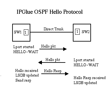
When a new direct trunk is created, Frame or ATM notifies OSPF with information on trunk type, bandwidth, VPN, etc. OSPF will then send out a 'hello' packet to get the IP address and configuration data from the node on the other side of the cable. Once a hello packet is received, the Link State Database is updated with this new information.
The following figure describes the simNet version of the hello protocol.
In simNet, the link state database is implemented as a linked list of entries, each entry representing a trunk, node, or circuit in the network. A trunk type entry is for ATM or Frame Direct trunks, and only these will be considered for PVC/SVC path candidate lists. Node type entries are for node prefix, port prefix and port address entries as supplied by the NMS and router address registration. These are supplied for name lookup and SHOW OSPF NAMES. Finally, PVCs and SVCs are added to the link state database and used for management paths when a static management path is not configured on a non gateway switch.
When flooding link state updates, simNet sends the entire link state database (probably not the most efficient, but..). Each entry in the database contains an AGE field. When ever a link is updated, the AGE field is incremented. When a switch receives a link state update, it compares the age fields of all the entries received with the age field in its own database, updating only the ones that changed. It then floods this database out to all other nodes except the one it received the update from.
Other parts of the OSPF specification are not implemented. Aging of entries, periodic flooding, etc are completely unnecessary for this simulation.
OSPF uses a technique called reliable flooding to propagate the link state database information throughout the network. This is well documented in standard publications, so this will be a brief description.
The following diagram describes the starting state of our example. Trunk 1 between Sw1 and Sw2 is up, as is Trunk 3 between Sw3 and Sw4. The link state databases for all switches represent this information. A note on the notation used for the Link State Database in these diagrams:
			Sw3 = Sw4 -> Sw3:2
	      	              Sw2 -> Sw3:1

		- Where Sw3 is the advertising router (or the switch
	  	  that generated the LSDB entry.
		- Sw4 -> Sw3:2 means that there is a link to Sw4 through
	  	  Lport Sw3:2
		- Sw2 -> Sw3:1 means that there is a link to Sw2 through
	    	  Lport Sw3:1
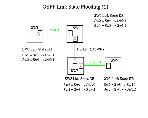
When Trunk 2 becomes active, Sw2 and Sw3 exchange Hello packets and find out the IP address of each end. They then update their link state databases. In this example, Sw2 becomes active first, flooding its link state database to Sw1, which updates his, and Sw3 which updates his and floods it to Sw4. Sw4 and Sw1 take no further action.
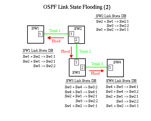
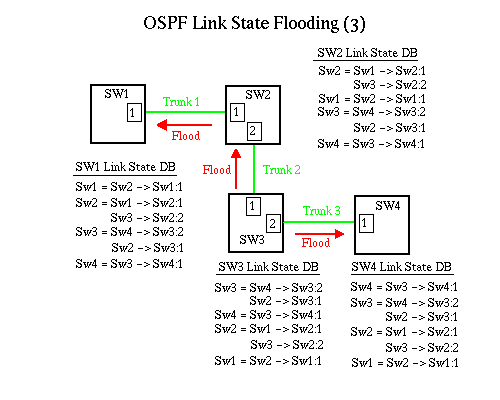
Finally, OSPF on Sw3 is informed of the new trunk becoming active and adds the link to its link state database. It floods this information to Sw4, which adds it and to Sw2. Sw2 adds it to its link state database and floods the database to Sw1, which updates its link state database. When this is complete, each switch has a link state database that is representative of the state of the network. This is then used by the Dijkstra algorithm to calculate least cost paths for the VC Manager.
OSPF needs to be notified of most trunk state changes, in order to let all other switches update their link state databases. Each of these state changes result in different actions for both OSPF and the VC Manager for all switches in the simulation.
As described above, transitioning into a ifOperStatus of UP results in all switches being notified of the new trunk. Along with this is passed the cost metric, available bandwidth for each QoS for the trunk, any associated VPN numbers, congestion state, Cell Delay Variation, and other information. This is used by OSPF on all switches to find best paths for the VC Manager.
The transition to ifOperStatus of DOWN, either through failure or manual intervention, results in a link state database flood to remove the trunk entry from all databases. OSPF also invokes the VC Manager at this time to see if it was the initiator of any circuits that transited this trunk. If so, the VC Manager may reroute those PVCs.
When the trunk becomes congested for lportCongestionCheckInterval , and if Closed Loop Congestion Control (CLCC) is enabled, OSPF will notify all switches. Each switch then notifies the VC Manager to check for CLCC. This notification also happens on transition out of congested state.
Not sure of thisWhen a circuit is provisioned through a node, available bandwidth for the requested QoS is decremented from the total available bandwidth for the trunk. OSPF floods this information to allow current bandwidth state of each trunk to be considered when allocating circuits.
OSPF is called by the Virtual Circuit Manager (VC Manager) to find a 'best' candidate path of trunks through a network, given its current knowledge of the topology of the network. For Frame Relay circuits, this best candidate path is based solely on the cost metric (Administrative Weight). For ATM a more complex, constraint based algorithm is required. For example, best path now may mean least cost and lowest delay. In general, Dijkstra can not solve shortest path problems having multiple constraints and multiple dimensions. However, solutions to approximate optimal routes can be arrived at through combining several constraints into a single metric and pre-filtering network links to simplify permutations.
Once this candidate path is found, it is the responsibility of the VC Manager to verify the path. Since OSPF topology information may be stale, the candidate path returned may not actually meet the QoS requirements for that circuit.
The following section describes the various parameters and constraints used for best path calculations. These values are initialized when the trunk is created and passed to each switch in the simulation via reliable flooding.
Administrative Weight is provisioned by the student for each trunk, and is the main metric used for the Dijkstra calculation. For Frame Relay, it is the only metric. For ATM, the path with the lowest Administrative Weight, given all the following constraints and pre-filters, is considered the best cost path.
When the trunk is created, the student has the ability to provision percentages of the virtual available bandwidth (forward and reverse) to each Quality of Service. This also allows for over-subscription of a trunk, where the virtual bandwidth is greater than the physical datarate of the trunk.
As new circuits are created, some portion of the available bandwidth for each trunk they transit is removed from the available bandwidth of that trunk. This information is eventually transmitted to every node in the simulation via a link state update. OSPF works closely with the VC Manager to ensure that there is enough bandwidth for each new circuit.
OSPF is notified of bandwidth changes when the VC Manager or ATM or Frame Relay layer call OSPF_LinkCostChange().
OSPF will use other metrics to determine the best candidate through a network, then test that path to see if it meets the bandwidth/QoS requirements. If it fails this test, OSPF will still return the best candidate path to the VC Manager, with a failure notification specifying the link that failed the bandwidth/QoS test. The VC Manager will then decide if other, lower priority circuits can be rerouted, or if the QoS requirements of this circuit can be modified.
The static delay of a link (lportTrkStaticDelay)is the interval required to send a packet one way over the link. In Lucent switches, this is measured when the trunk comes up. For the simulation, this will be an IOS supplied constant for the media type varied depending on the physical cable length (pportLineBuildOut??).
Dynamic delay ( lportTrkDynamicDelay) is usually equal to the static delay, except in congestion situations where queueing of packets is involved. The Media handlers in the Physical layer will adjust this value by some small percent depending on queue size. The Labs currently do not use Dynamic delay.
When the Dijkstra algorithm is run, a running total of the static delay of a given path is kept. If this exceeds the maximum for the requirements of the circuit, a different path is chosen.
If a circuit requests a Virtual Private Network (VPN), only trunks with a matching VPN number can be considered for the candidate path. OSPF will pre-filter its Link State Database so that only links with the requested VPN are seen for the Dijkstra calculations.
A trunk Customer ID VPN of zero is considered a public trunk. A circuit requesting VPN of zero can consider all public trunks. However, it can not transit non-zero VPN trunks. A circuit with a non-zero VPN can only transit trunks with matching VPN numbers, unless cktXXXFILLMEIN is enabled. In that case, public trunks can also be considered if bandwidth is not available on VPN trunks.
Each trunk can limit its traffic to management traffic only, user traffic only, or both. When setting up a circuit, OSPF will pre-filter the Link State Database so that only user traffic (or both) link types are considered.
This traffic type can change dynamically (Lab xx in Frame II). The VC Manager and Frame/ATM layers need to validate each packet against this setting.
The VC Manager can supply a list of trunks (as a node IP/IfIndex pair) to avoid in the calculation of a path. For various reasons (bandwidth/QoS limitations, rerouting and load balancing, priority bumping, etc), the VC manager has determined that these links are not to be used in the candidate path. These links are pre-filtered from the Link State Database, and the Dijkstra algorithm ignores them.
See the VC manager chapter for more information on this interaction.
OSPF finds the best cost path to a destination node using the above constraints and pre-filters. It then tests this path against available bandwidth. In some cases, multiple equal cost paths may exist to the destination node. In these cases, OSPF will select the path with the largest available total bandwidth. This total bandwidth is actually the minimum available bandwidth of all the path's constituent trunks.
The VC Manager is responsible for supplying OSPF with correct requirements for the circuit, testing the validity of the returned candidate path, and rerouting other circuits or changing circuit requirements to complete circuit setup. This is covered in more detail in the VC Manager chapter.
Connection Admission Control (CAC) is a set of algorithms that determine the effective bandwidth utilization of a circuit. When a circuit is created, several parameters are supplied that describe its traffic requirements. These parameters include the Sustained Cell Rate (SCR), Peak Cell Rate (PCR), the Maximum Burst Size (MBS), Cell Transfer Delay (CTD), Cell Delay Variation (CDV) and Cell Loss Ratio (CLR). These requirements describe the Quality of Service of the circuit.
CAC uses these supplied parameters to statistically maximize the available bandwidth of the network while still meeting the QoS requirements of each circuit. It does this by using PCR, SCR and MBS to calculate an effective bandwidth of the circuit. In most cases, this is some value between SCR and PCR. This allows a circuit to reserve less bandwidth than it can legally burst, allowing more circuits per trunk. This CAC calculated effective bandwidth is passed to OSPF when finding the best candidate path.
CAC also tests each new circuit on a node by node basis, to ensure that the supplied path (which may have been stale) meets the circuit QoS requirements given actual current state of the node.
CAC is an important competitive differentiator for Lucent, as an aggressive CAC algorithm can allow more circuits per trunk when correctly configured. Further discussion of this can be found in the VC Manager chapter.
Standard OSPF will calculate the best path to a destination switch for a single metric, usually an adminstrativly assigned weight or cost for each link. To do this, OSPF uses the well defined Dijkstra algorithm. However, for best path calculations where QoS, bandwidth, cell delay and transit time are factors, the Dijkstra algorithm is insufficient. Lucent uses a combination of the Dijkstra algorithm, backtracking, link state pre-filtering and constraints on the Dijkstra algorithm to find the best path through ATM (and Frame Relay with priority) networks.
Lingmian/Tom/Chas: This is the way I would implement this if I was still doing OSPF. From all the reading I've done of Lucent white papers and ATM Forum PNNI specs, this is the best way I can think of to match the functionality of VNN
When the VC Manager gets a request to set up a circuit to another switch (PVC or SVC), it calls Ospf_FindCandidatePath() with the requirements of the circuit. These requirements include an effective bandwidth (CAC calculates this using the SCR, PCR and MBS of the circuit), the cell delay tolerances, any VPNs (Virtual Private Networks), the required Quality of Service, and a list of links (trunks) to avoid, if any.
The Dijkstra algorithm uses information on network topology from the link state database to build a spanning tree of least cost (best) paths to every other node in the network. It does not keep every path to every node in the network, only the best path. Since there are now different considerations for finding the best path, depending on the type of circuit requested, the Dijkstra algorithm must run every time a new path is needed.
Dijkstra starts out with an empty spanning tree. The first node (our root node) is added. Then all links out of this node (as defined in the Link State Database entry for this node) are considered for the Dijkstra Candidate Stack.
Candidates for the Dijkstra Candidate Stack are limited (pre-filtered) to include:
- If the link state entry for the node the link points to is beyond max age, or the node the link points to does not have a valid link back to this node,ignore it
- If the link NodeIp/IfIndex is in the Avoid List, ignore it
- If the VPN number of the circuit is zero (public) and the link has a non-zero VPN number (private), ignore it
- If the VPN number of the circuit is non-zero and the link VPN number does not match, ignore it. The exception is if overflow is enabled and the VPN of the link is zero. In that case, the link may be considered as a candidate for the Dijkstra Candidate stack
- If this link is already on the spanning tree, ignore it
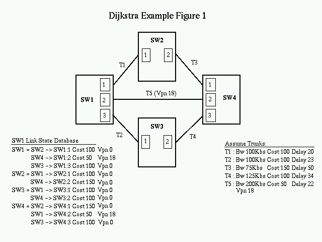
In the example, SW1 is looking for a best path to SW4 on a public VPN. On the first pass through the Dijkstra loop, we put SW1 as the root node of the spanning tree, and edges T1 and T2 are added to the candidate list. Edge T5 is pre-filtered since it does not meet the VPN criteria.
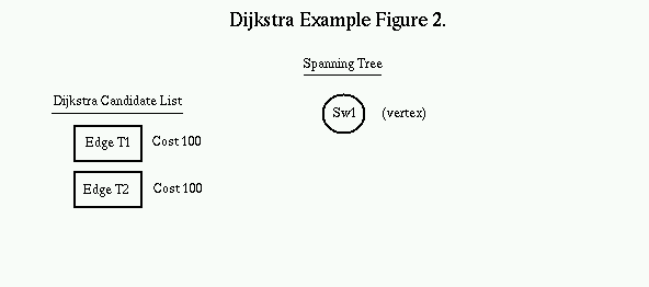
The Dijkstra Candidate list is always kept in sorted order. The first item is popped off the list and placed on the Spanning tree, with the switch on the other side of the link becoming the new Vertex. The process is repeated with SW2 as the new vertex. All valid links off of SW2 are added to the candidate list.
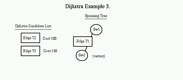
Again, the top of the candidate list (edge T2) is popped off the list and the edge and node it points to is added to the tree. The new node (SW3) now becomes the vertex. All valid links off of SW3 are now added to the candidate list. Note that the destination switch of edge T4 is the same as edge T3. Since the edge T4 costs less, it replaces edge T3 on the candidate list.
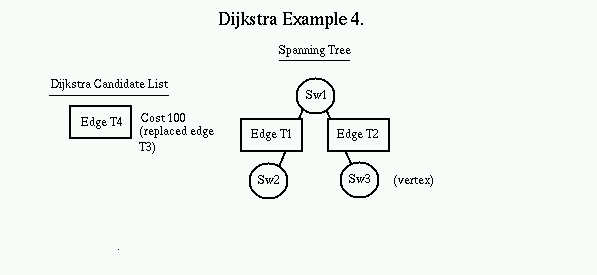
Again, the top of the candidate list is popped and added into the tree where it belongs, with its destination switch, and its destination switch becomes the vertex. The new vertex is searched for candidates, and since all links are already on the tree, no candidates are found. When the candidate list is empty, the tree is completely populated.
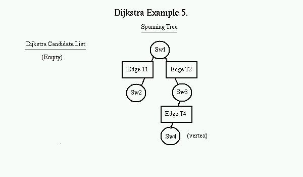
Note that although Edge T5 presented the least cost path from SW1 to SW4, it was not a public VPN and therefore was pre-filtered before being added to the candidate list. Also note that the next cost path through edge T3 is not on the spanning tree. This means that for every change in the topology of the network, each switch may have to recalculate its spanning tree.
Given the above tree, assume that edge T4 becomes congested. This would be detected at Lport SW2:2. The VC Manager may choose to reroute some circuits over a different, higher cost path avoiding the edge T4. In this case, the VC Manager calls Ospf_FindCandidatePath() with SW2:2 as an avoid link.
Again, SW1 as added as the root node. All valid edges from it (edge T1 and T2) are put on the candidate list in cost sorted order. The top of the list is popped off and placed on the tree. This becomes the vertex node. All of its edges are examined and valid ones are put on the candidate list. See Dijkstra Example Figure 3.
The top of the candidate list (Edge T2 to SW3) is popped off and placed on the tree. SW3 becomes the vertex node. However, since edge T4 (SW2:2) is on the avoid list, it is not considered for the candidate list and never replaces the higher cost edge T3 (as in the above example).
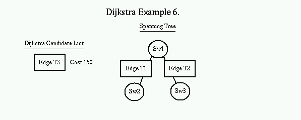
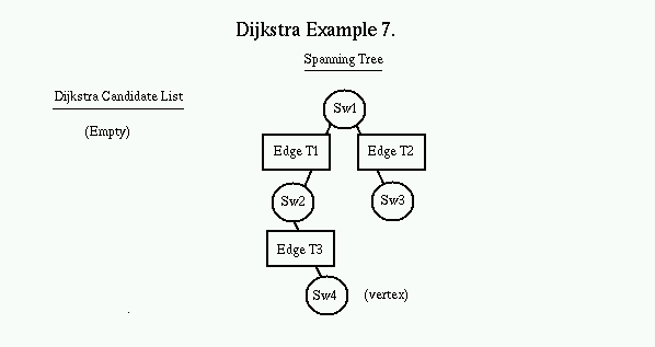
Sw3 contributes no valid links to the candidate list. The top item is removed from the list and placed on the spanning tree. This is the higher cost path through edge T3. Edges are considered off of the new vertex. There are none and the candidate list is empty, so the tree is complete.
The key to the modifications of the standard Dijkstra algorithms to meet the requirements of ATM QoS routine lies in pre-filtering edges from the Link State Database before considering them for the candidate list, deciding which criteria to use for sorting of the candidate list, and the interaction with the VC Manager to 'backtrack' and avoid various nodes if they fail CAC.
Depending on the needs of the VC Manager and the needs of the circuit, links can be rejected for the candidate list because they don't meet VPN, bandwidth, congestion, or cell delay variation needs. Once they have been accepted, they can be put on the candidate list in cost order, or in cumulative cell transit delay order, or whatever the needs of the request are.
Ospf_FindCandidatePath() returns a the best possible path given the constraints supplied by the VC Manager. Available bandwidth of each link in the path is one of those considerations. Through reliable flooding, OSPF has knowledge of the available bandwidth of every link in the network. As a best candidate path is found, it is checked against the bandwidth needs of the circuit. If a link along the path does not have the available bandwidth to meet the needs of the circuit, the path is still returned to the VC Manager, with a flag indicating the limiting link.
The VC Manager at this point makes a decision to A)reroute a lower priority circuit to a higher cost path to free up bandwidth across the limiting link, B)lower the QoS of the new requesting circuit and go call Ospf_FindCandidatePath() again, C)call Ospf_FindCandidatePath() with the limiting link as an avoid link, or D)return a 'path unavailable' message to the requester.