Radio Modulation
Jim Blakey - N2MQE
Often in the consulting business we find ourselves dealing with
some sort of radio related work. So for this article I decided to write
up a quick review of some of the basics of radio theory.
Radio communications in its most basic sense is simply an agreement
between a transmitter and a receiver. The transmitter transmits an
oscillating energy wave at an agreed on frequency, lets say 100MHz, and
the receiver filters out everything that is not 100MHz and amplifies what's
left. This agreed on oscillation frequency is called a carrier wave
and, by itself, carries no actual information. But without being able to
transmit information, radio would be useless. The act of modifying the
carrier wave to carry useful information is called modulation
and the following sections discuss the various ways carrier waves are
modulated to encode information.
Carrier Wave Modulation
- On Off Keying (OOK) Modulation
The most basic way of encoding information on a carrier wave is
to simply turn it on and off. This is called Carrier Wave (CW) modulation
and is still in limited use today. The very first Morse code radios worked
in this way. Morse code was a way to encode the alphabet as a series of
on-off sequences.
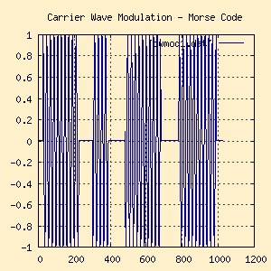
The below figure shows the single letter A as a Morse code
"Dah - Dit - Dah - Dah" sequence coded on a carrier wave.
Amplitude Modulation
- Math behind Amplitude Modulation
-
Amplitude Modulation is one of the earliest methods of encoding useful
information on a carrier wave. Remember, the goal is to modify the carrier
wave with some waveform that contains information we wish to transmit.
The waveform that contains the information we wish to transmit (voice, data,
fax, etc) is called the modulating waveform. The simplest way to do this is
with a hardware mixer that multiplies the carrier wave with the modulating
wave. A mathematical representation of this with two sine waves is:

Ok, that's simple enough but there's an interesting property that can
only be explained by expanding the math a little. Bear with me a little.
Remember from basic trigonometry that the product of two sine waves can
also be expressed as:

So now if we plug the amplitude of the carrier and modulation waves
(ampc and ampm) and the frequencies of the carrier
and modulation waveforms (freqc and freqm) into
the above equation we get:

This now leaves us with two distinct and different sine waves, one at
the difference between the carrier and modulation frequencies and one at
the sum of the carrier and modulation frequencies. This becomes noticeable
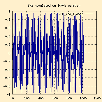
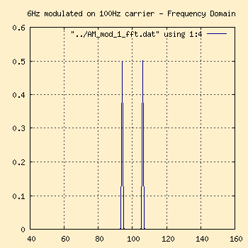
when you look at it in the frequency domain. In the following two figures,
I've modulated a 6Hz wave on a 100Hz carrier.
 Time Domain |
 Frequency Domain |
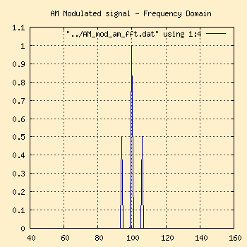
Notice on the frequency domain graph on the right that there are two
different frequencies, 94Hz (6Hz below the carrier frequency of 100Hz) and
106Hz (6Hz above the carrier frequency). These are called the side bands
and are where all the information in the signal (voice, data, etc) is
carried. The waveform higher than the carrier frequency which is the sum
product of the carrier and modulation waves is called the
Upper Sideband (USB) and the one below the carrier frequency which
is the difference product of the carrier and modulation waves is
called the Lower Sideband (LSB)
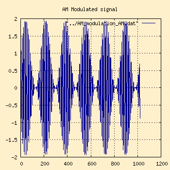
Now, if we re-inject the AM carrier frequency back into the picture,
we have a complete AM signal that looks like:
 Time Domain |
 Frequency Domain |
Notice how the signal shape changed when the original carrier frequency
was added back in, now more closely corresponding to the modulating wave's
shape. This is called the Modulation Envelope of the signal, and is
characteristic of an AM signal. However, it is easy to be mislead by the
time domain graph into thinking that the carrier wave itself varies with
the intensity of the modulating wave. This is not the case as the frequency
domain graph on the right shows.
- Sidebands
-
Since an AM signal's entire informational content is contained in the
sidebands, and that the upper and lower sidebands contain duplicate information,
it follows that there is no real need to waste the energy and spectrum space
in sending the carrier and both sidebands. Therefore, there are several ways
to modify the AM signal.
- Double Sideband, Full Carrier (DSB)
This is the standard AM broadcast signal, with commercial radio
stations operating in the 525 to 1705KHz range. None of the
signal is suppressed in this format. This is seen in the above
figures
- Double Sideband, Suppressed Carrier
The carrier frequency is suppressed in the transmitter before
the signal is transmitted
- Single Sideband (SSB), suppressed carrier
Only one of the two sidebands is transmitted, the carrier and
other sideband is suppressed. Either sideband (USB or LSB) can
be sent
- Single Sideband (SSB), full carrier
Also called AM Equivalent (AME) and has some commercial and
military applications. Only one of the sidebands is suppressed,
the carrier and other sideband are transmitted.
- Independent Sideband (ISB)
- Both sidebands are sent, but contain a different signal. Essentially,
two different SSB signals on same carrier frequency.
|
- AM Bandwidth
-
In the above examples, I used a simple 6Hz modulation sine wave as
our example. This gave us sidebands 6Hz above and below the 100Hz carrier.
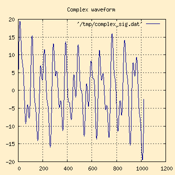
What happens if we have a more complex waveform we're modulating, as would
be the normal case in the real world? The waveform on the left graph below
contains 8 different frequencies: 5Hz, 7Hz, 11Hz, 12Hz, 14Hz, 19Hz, 22Hz, and
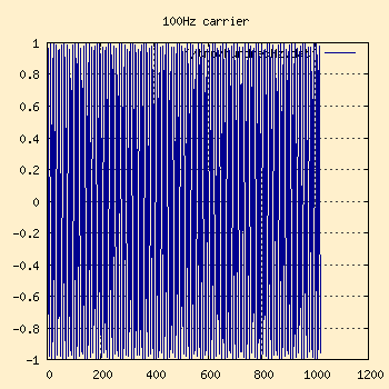
30Hz, all at different amplitudes. These will be modulated with the
100Hz wave in the right hand graph.
 Modulation wave |
 Carrier Wave |
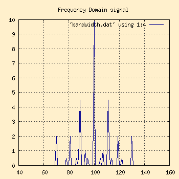
Now modulate these waves and look at the frequency domain response.
Notice the 100Hz carrier spike? The bandwidth is how far to either side
of that carrier spike the sidebands go. Basically, since the highest
frequency in the modulated wave was 30Hz, the bandwidth for that signal
will need to be at least 30Hz on either side of the carrier to keep information
from getting lost. The more information the signal carries (30Hz worth in
this case), the wider the sidebands will be and the wider the bandwidth will be.
Frequency Modulation
- The Math of FM Modulation
-
The math behind Frequency modulation is a little more complicated than
AM. FM is a type of Angular Modulation, along with Phase Modulation (PM).
These are so similar that I'll cover them together. Remember that any
given carrier wave can be generated with the formula

From this we can see that there are only 3 ways to modulate a carrier
wave, by modifying its amplitude (as we did above with AM), its frequency
or its phase. Angular modulation replaces either the frequency or phase
of the above carrier wave formula with the instantaneous amplitude of
the modulation waveform at time t.
So if our modulation wave is a sine wave represented by the formula

Then the equation for modulating our carrier for FM would be

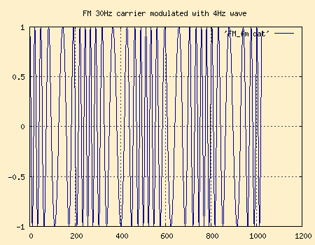
A typical FM modulated signal with a 30Hz carrier and a 4Hz modulation wave
in the time domain would look something like this.
I'll discuss the new constant m in a minute, but first we will
expand out the math as we did in the AM section above to see how the sidebands
break out in FM. Again, using basic trig:

So in the expanded form of the FM equation you can see how upper and
lower sidebands are generated. However, these are completely different
mathematically from the AM sidebands, and lead to some interesting side
effects that are discussed below.
- FM Sidebands, Bandwidth and the Modulation Index
-
The above equations introduced the constant m. This is called
the Modulation Index and is an integral part of any FM or Angular Modulation
system. The Modulation Index is defined as the Peak Deviation Frequency
(i.e. the maximum frequency deviation from the carrier) divided by
the maximum Modulation frequency (i.e. the maximum frequency in the
modulation wave).

A better way to describe the Peak Deviation Frequency would be
how far we will let the sidebands swing out from the carrier center point. For
example, the FCC limits commercial FM radio stations to a 200KHz slice
of the spectrum. Of that, 25KHz on either side must be buffer space.
Therefore, a commercial FM radio station has a 75KHz Peak Deviation
Frequency on either side of their carrier center frequency they're allowed
to play in. Given that FM audio signals (i.e. the modulation waveforms)
go from about 20Hz to about 15KHz, the maximum Modulation Frequency
would be 15KHz. To find an appropriate Modulation Index:
m = 75,000 / 15,000
Unlike AM, an FM signal actually has in infinite number of sidebands.
Theoretically, this would lead to total chaos on the airwaves. Fortunately,
in practice most of these sidebands are weak and disappear in the mud. But
the strength of these sidebands relative to the carrier varies with the degree
of modulation. This is controlled with the Modulation Index.
Carson's Rule is a formula that approximates bandwidth requirements
of a signal and states that, even though there are an infinite
number of sidebands in FM signals, approximately 98% of the energy in
those signals is contained within the bandwidth defined by:

Hopefully, a few examples will make this clearer. I'm going to modulate
a 50Hz carrier wave against a 5Hz modulation sine wave. For each, I'm going
to vary the Modulation Index. By varying the Modulation Index, I am effectively
varying the Peak Deviation of the signal as well, so we'll see how both the
Modulation Index and Carson's Rule work together.
Notice how the modulation index effects the "swing" of the modulated
signal around the carrier center point. This will be especially visible
in the frequency domain as the width and number of sidebands increases
with the modulation index.
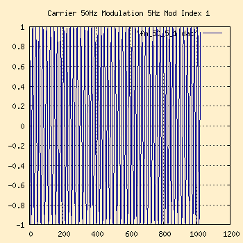
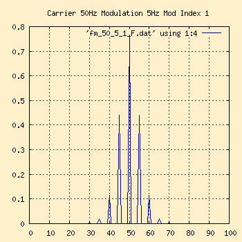
50Hz Carrier, 5Hz Modulation, Modulation Index 1
 Time Domain |
 Frequency Domain |
This would be considered narrow band FM. Notice how in the time
domain you can barely make out the modulation patterns. In the frequency
domain chart, we have a Peak Deviation of 5Hz (from a modulation index of
1) and a modulation frequency of 5Hz, so per Carson's Rule we'd expect 98%
of the sidebands gone within a bandwidth of 2*(5+5) around the carrier
frequency of 50Hz.
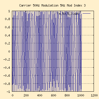
50Hz Carrier, 5Hz Modulation, Modulation Index 3
 Time Domain |
 Frequency Domain |
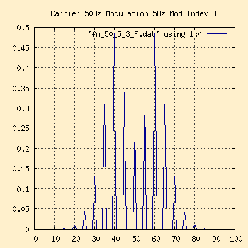
The bandwidth is higher in this one. The modulation pattern is now
just becoming visible in the time domain chart. In the frequency domain
chart, we now have a Peak Deviation of 15Hz (from modulation index of 3)
and still the modulation frequency of 5Hz, giving us 2*(15+5) = 40Hz around
the 50Hz carrier.
50Hz Carrier, 5Hz Modulation, Modulation Index 5
 Time Domain |
 Frequency Domain |
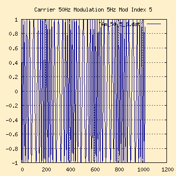
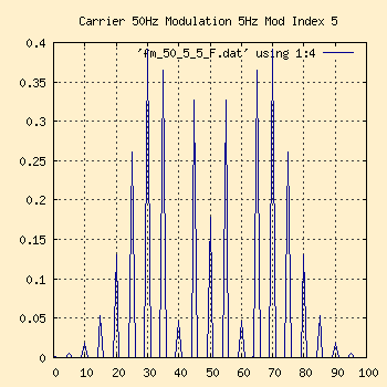
Finally the modulation pattern is visible in the time domain. The
Peak Deviation is 25Hz, giving us a Carson bandwidth approximately 60Hz
around the 50Hz carrier center point.
- FM Stereo Implementation
-
The previous discussion of FM was all about mono modulation. This
was the first mode of FM broadcasts. In the late 1950's engineers started
to work on systems for broadcasting in stereo, and the first commercial
stereo FM system was approved in 1961. This system had to meet several
requirements, mainly old mono FM receivers still had to work with it and
it couldn't stray out of the existing FM spectrum allocations.
Stereo signals contain a left channel and a right channel (L and R).
In order for the old mono FM receivers to continue to work, the original
20Hz to 15KHz part of the audio signal had to remain the same. This now
contains both the Left and Right channel, added together (L+R). A second
signal with the Left and Right subtracted (L-R) is also broadcast and
stereo receivers can use this to mathematically recover the individual
Left and Right channels.
This second (L-R) signal is Amplitude Modulated on a 38KHz
sub-carrier wave. The 38KHz sub-carrier is suppressed, leaving
only the upper and lower sidebands extending +/-15KHz from the 38KHz
center. A 19KHz Pilot tone is injected to separate the (L+R)
and the (L-R) channels.
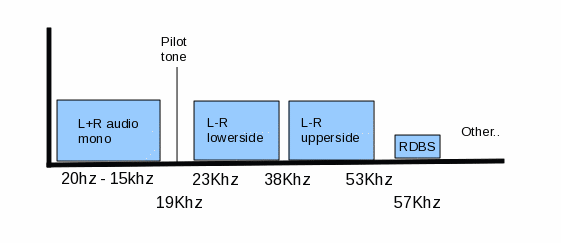
The 19KHz Pilot tone serves several interesting purposes. First, it acts
as a signal to stereo receivers that a stereo encoded signal is present.
Since it is above the 15KHz that old mono receivers can hear, it won't
cause interference with them. Secondly, it is exactly one half the 38KHz
AM sub-carrier frequency used to modulate the (L-R) signal. This allows
the radio to just double the Pilot tone frequency to de-modulate the
(L-R) signal. This is much easier and more reliable than trying to generate
a local 38KHz wave, as any drift or inaccuracy would cause the (L-R) signal
to be degraded. In other words, just use the exact same waveform that the
transmitter used in modulating the (L-R) signal.
Next, since our maximum Modulation Frequency has now jumped from
15KHz to at least 53KHz, the Modulation Index for the FM signal now has to
be adjusted. It is now closer to 1 than 5.
Also note that other services may reside above the 53KHz top end of
the stereo signal. RBDS (Radio Broadcast Data System) for example resides
at the third harmonic of the 19KHz Pilot tone. This is used to send
station identifiers and other text information. It is very low bandwidth.
|


